Module 5 – Lab 1: OSPF Configuration
What you will learn: In this lab, you will learn how to set up OSPF (Open Shortest Path First) on three routers by giving them IP addresses, creating loopback interfaces, and turning on OSPF. You will also check if the routers are connected, see their OSPF neighbors, and test if they can communicate with each other for successful end-to-end communication.
You are a network engineer tasked with configuring a simple OSPF (Open Shortest Path First) routing protocol in a triangular topology involving three routers:
- Router 1
- Router 2
- Router 3
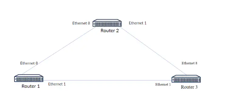
The routers are connected via Ethernet interfaces, as shown in the diagram.
Instruction
Step 1: Assign IP Addresses on all of the Routers.
Log in to the switches (Router 1, Router 2, Router 3) using the default credentials, use the Klish CLI. Assign a proper IP Addressess to each of the port that is connected to other Router. Create an Loopback interface and assign a IP address to that interface.
Router 1:
- Ethernet 1 – 1.1.1.1/31
- Ethernet 8 – 1.1.1.2/31
- Loopback0 – 192.168.0.1/32
Router 2:
- Ethernet1 – 1.1.1.4/31
- Ethernet8 – 1.1.1.3/31
- Loopback0 – 192.168.0.2/32
Router 3
- Ethernet1 – 1.1.1.0/31
- Ethernet8 – 1.1.1.5/31
- Loopback0 – 192.168.0.3/32
Step 2: Create OSPF and Configure a router id for the OSPF process.
After you configured all of the interfaces on the router, you need to create an OSPF on a every router and configure a proper router-id on every OSPF session.
Step 3: Verify OSPF Configuration
To see if your configuration is properly applied, you need to first check in SONiC if the sessions
between the routers stays up. To do that, type in console “show ip ospf” and “show ip ospf neighbor”
Step 4: Check the connectivity between the routers.
From each router, ping the interfaces of the other two routers to confirm end-to-end connectivity.
Hints and tips
- Default credentials: admin / YourPaSsWoRd
- Remember to add passive-interface command to your OSPF configuration to Loopback interface
- Be cautious about the OSPF area that you are using – It must match in this scenario between the switches.
- The names of the virtual computers are different in remote access to those shown on the topology. Virtual computers and their counterparts in remote access are motioned below:
- Router1 – mod5lab1-sw1
- Router2 – mod5lab1-sw2
- Router3 – mod5lab1-sw3
Answer
The purpose of the laboratory is to practice creating MCLAGs and PortChannels and how to use them in real environment.
Step 1: Assign IP Addresses on all of the Routers.
Router 1
interface Loopback 0
 ip address 192.168.0.1/32
interface Ethernet1
 ip address 1.1.1.1/31
 no shutdown
interface Ethernet8
 ip address 1.1.1.2/31
Router 2
 interface Loopback 0
 ip address 192.168.0.2/32
interface Ethernet1
 ip address 1.1.1.4/31
 no shutdown
interface Ethernet8
 ip address 1.1.1.3/31
 no shutdown
Router 3
interface Loopback 0
 ip address 192.168.0.3/32
interface Ethernet1
 ip address 1.1.1.0/31
 no shutdown
interface Ethernet8
 ip address 1.1.1.5/31
 no shutdown
Step 2: Configure OSPF on Router 1, Router 2 and Router 3.
Router 1
router ospf
ospf router-id 192.168.0.1
area 0.0.0.1
network 1.1.1.0/24 area 0.0.0.1
network 192.168.0.1/32 area 0.0.0.1
passive-interface Loopback 0
Router 2
router ospf
ospf router-id 192.168.0.2
area 0.0.0.1
network 1.1.1.0/24 area 0.0.0.1
network 192.168.0.2/32 area 0.0.0.1
passive-interface Loopback 0
Router 3
router ospf
ospf router-id 192.168.0.3
area 0.0.0.1
network 1.1.1.0/24 area 0.0.0.1
network 192.168.0.3/32 area 0.0.0.1
passive-interface Loopback 0
Step 3: Verify OSPF Configuration
show ip ospf example:
sonic# show ip ospf
OSPF Routing Process, Router ID: 192.168.0.1
Supports only single TOS (TOS0) routes
This implementation conforms to RFC2328
RFC1583Compatibility flag is enabled
OpaqueCapability flag is disabled
Initial SPF scheduling delay 0 millisec(s)
Minimum hold time between consecutive SPFs 50 millisec(s)
Maximum hold time between consecutive SPFs 5000 millisec(s)
Hold time multiplier is currently 1 time is 92031756
SPF algorithm last executed 1065d4h22m ago
Last SPF duration 0.0s
SPF timer is inactive
LSA minimum interval 5000 msecs
LSA minimum arrival 1000 msecs
Write Multiplier set to 20
Refresh timer 10 secs
Number of external LSA 0. Checksum Sum 0x0
Number of opaque AS LSA 0. Checksum Sum 0x0
Number of areas attached to this router: 2
Area ID: 0.0.0.1
Number of interfaces in this area: Total: 2 , Active: 2
Number of fully adjacent neighbors in this area: 0
Area has no authentication
SPF algorithm executed 1 times
Number of LSA 2
Number of router LSA 0. Checksum Sum 0x0
Number of network LSA 0. Checksum Sum 0x0
Number of summary LSA 2. Checksum Sum 0x40f1f61000000000
Number of ASBR summary LSA 0. Checksum Sum 0x0
Number of NSSA LSA 0. Checksum Sum 0x0
Number of opaque link LSA . Checksum Sum 0x
Number of opaque area LSA 0. Checksum Sum 0x0
Step 4: Check the connectivity between the routers.
Router 1:
# Ping Router 2's Loopback
ping 192.168.0.2
# Ping Router 3's Loopback
ping 192.168.0.3
# Ping Router 2's Ethernet Interface (1.1.1.4)
ping 1.1.1.4
# Ping Router 3's Ethernet Interface (1.1.1.0)
ping 1.1.1.0
Expected Output:
All pings should show success with low latencyRouter 2:
# Ping Router 1's Loopback
ping 192.168.0.1
# Ping Router 3's Loopback
ping 192.168.0.3
# Ping Router 1's Ethernet Interface (1.1.1.1)
ping 1.1.1.1
# Ping Router 3's Ethernet Interface (1.1.1.5)
ping 1.1.1.5
Expected Output:
All pings should show success with low latencyRouter 3:
# Ping Router 1's Loopback
ping 192.168.0.1
# Ping Router 2's Loopback
ping 192.168.0.2
# Ping Router 1's Ethernet Interface (1.1.1.2)
ping 1.1.1.2
# Ping Router 2's Ethernet Interface (1.1.1.3)
ping 1.1.1.3
Expected Output:
All pings should show success with low latencyModule 5 – Lab 2: BGP Configuration
What you will learn: In this lab, you will learn how to configure BGP (Border Gateway Protocol) on three routers by assigning IP addresses, setting up loopback interfaces, and configuring BGP with unique AS numbers. You will activate the IPv4 unicast address family, establish BGP neighbor relationships, and verify the setup using the appropriate commands. Finally, you will test connectivity between the routers to confirm successful end-to-end communication. Your goal is to establish BGP sessions between all routers and ensure end-to-end connectivity.
You are a network engineer tasked with configuring a simple BGP (Border Gateway Protocol) routing protocol in a triangular topology involving three routers:
- Router 1,
- Router 2
- Router 3.
The routers are connected via Ethernet interfaces, as shown in the diagram.
Instruction
Step 1: Assign IP Addresses on all of the Routers.
Log in to the switches (Router 1, Router 2, Router 3) using the default credentials, use the Klish CLI. Assign a proper IP Addressess to each of the port that is connected to other Router. Create an Loopback interface and assign a IP address to that interface.
Router 1:
- Ethernet 1 – 1.1.1.1/31
- Ethernet 8 – 1.1.1.2/31
- Loopback0 – 192.168.0.1/32
Router 2:
- Ethernet1 – 1.1.1.4/31
- Ethernet8 – 1.1.1.3/31
- Loopback0 – 192.168.0.2/32
Router 3
- Ethernet1 – 1.1.1.0/31
- Ethernet8 – 1.1.1.5/31
- Loopback0 – 192.168.0.3/32
Step 2: Create BGP on every router with different AS number and configure a router id for the BGP process
After you configured all of the interfaces on the router, you need to create an BGP process on a every router and configure a proper router-id on every router with created BGP session.
Step 3: Activate IPv4 unicast address-family and configure every neighbor.
Activate address-family on every BGP session – This must be done on the neighbours (IPv4 unicast address family). You will need to advertise local interfaces, also in the IPv4 unicast address-family.
Step 4: Verify BGP configuration.
You need to check the BGP configuration after the configuration – Make sure everything is set all right! To do that, you need to type in console “show bgp ipv4 unicast summary”
Step 5: Do the connectivity test.
From each router, ping the Loopback interfaces of the other two routers to confirm end-to-end connectivity
Hints and tips
- Default credentials: admin / YourPaSsWoRd
- Be cautious about the BGP AS number that you are using – In this case, it needs to be different!
- Double-check every IP address if they are assigned correctly!
- The names of the virtual computers are different in remote access to those shown on the topology. Virtual computers and their counterparts in remote access are motioned below:
- Router1 – mod5lab2-sw1
- Router2 – mod5lab2-sw2
- Router3 – mod5lab2-sw3
Answer
The purpose of the laboratory is to practice creating MCLAGs and PortChannels and how to use them in real environment.
Step 1: Assign IP Addresses on all of the Routers.
Router 1
interface Loopback 0
 ip address 192.168.0.1/32
interface Ethernet1
 ip address 1.1.1.1/31
 no shutdown
interface Ethernet8
 ip address 1.1.1.2/31
Router 2
 interface Loopback 0
 ip address 192.168.0.2/32
interface Ethernet1
 ip address 1.1.1.4/31
 no shutdown
interface Ethernet8
 ip address 1.1.1.3/31
 no shutdown
Router 3
interface Loopback 0
 ip address 192.168.0.3/32
interface Ethernet1
 ip address 1.1.1.0/31
 no shutdown
interface Ethernet8
 ip address 1.1.1.5/31
 no shutdown
Step 2 & 3: Create BGP on every router with different AS number, configure a router id for the BGP process, activate address-family and configure every neighbor.
Router 1
router bgp 65100
 router-id 192.168.0.1
 address-family ipv4 unicast
  redistribute connected
neighbor 1.1.1.0
remote-as 65102
address-family ipv4 unicast
activate neighbor 1.1.1.3
remote-as 65101
address-family ipv4 unicast
activateRouter 2
router bgp 65101
 router-id 192.168.0.2
 address-family ipv4 unicast
  redistribute connected
neighbor 1.1.1.2
remote-as 65100
address-family ipv4 unicast
activate neighbor 1.1.1.5
remote-as 65102
address-family ipv4 unicast
activateRouter 3
router bgp 65102
 router-id 192.168.0.3
 address-family ipv4 unicast
  redistribute connected
neighbor 1.1.1.1
remote-as 65100
address-family ipv4 unicast
activateneighbor 1.1.1.4
remote-as 65101
address-family ipv4 unicast
activateStep 4: Verify BGP Configuration
show bgp ipv4 unicast summary example:
sonic# show bgp ipv4 unicast summary
BGP router identifier 1.1.1.1, local AS number 100
Neighbor    V AS MsgRcvd MsgSent InQ OutQ Up/Down State/PfxRcd
192.168.0.2 4 200 18480  18486    0 0      1w5d19h     8
192.168.0.3 4 200 18510  18502    0 0     02:49:01     11
Step 5: Check the connectivity between the routers.
Router 1:
# Ping Router 2's Loopback
ping 192.168.0.2
# Ping Router 3's Loopback
ping 192.168.0.3
# Ping Router 2's Ethernet Interface (1.1.1.4)
ping 1.1.1.4
# Ping Router 3's Ethernet Interface (1.1.1.0)
ping 1.1.1.0
Expected Output:
All pings should show success with low latencyRouter 2:
# Ping Router 1's Loopback
ping 192.168.0.1
# Ping Router 3's Loopback
ping 192.168.0.3
# Ping Router 1's Ethernet Interface (1.1.1.1)
ping 1.1.1.1
# Ping Router 3's Ethernet Interface (1.1.1.5)
ping 1.1.1.5
Expected Output:
All pings should show success with low latencyRouter 3:
# Ping Router 1's Loopback
ping 192.168.0.1
# Ping Router 2's Loopback
ping 192.168.0.2
# Ping Router 1's Ethernet Interface (1.1.1.2)
ping 1.1.1.2
# Ping Router 2's Ethernet Interface (1.1.1.3)
ping 1.1.1.3
Expected Output:
All pings should show success with low latencyModule 5 – Lab 3: Static Routes Configuration
What you will learn: In this lab, you will configure static routing in a linear topology with three routers to ensure full connectivity. You will manually define routes on each router and implement a blackhole static route for network stability. Finally, you will verify the configuration using the routing table and test end-to-end connectivity.
You are a network engineer tasked with configuring static routing in a linear topology involving three routers: R-1-1, R-1-2, and R-1-3. The routers are connected via Ethernet interfaces, as shown in the diagram. Your goal is to ensure full connectivity between all routers by configuring appropriate static routes on each device.
- Router R-1-1 is connected to Router R-1-2 via interface e1 with IP addresses 192.168.1.2 (R-1-1) and 192.168.1.1 (R-1-2).
- Router R-1-2 connects to Router R-1-3 via interface e2 with IP addresses 192.168.2.1 (R-1-2) and 192.168.2.2 (R-1-3).
Instruction
Step 1: Assign IP Addresses on all of the Routers
Log in to the routers (R-1-1, R-1-2, R-1-3) using the default credentials and use the CLI. Assign the correct IP addresses to each Ethernet interface that connects to another router.
Router R-1-1:
- Ethernet1 – 192.168.1.2/24
Router R-1-2:
- Ethernet1 – 192.168.1.1/24
- Ethernet2 – 192.168.2.1/24
Router R-1-3:
- Ethernet2 – 192.168.2.2/24
Step 2: Configure Static Routes on each Router + additional floating static route to 192.168.3.0 to blackhole
After assigning IP addresses, configure static routes to ensure connectivity between all routers. Create additional static route to 192.168.3.0 remember – It needs to be blackhole!
Step 3: Verify Static Route Configuration
After configuring the static routes, verify the configuration on each router using command “show ip route”. Could you tell what the letters means under “Codes”?

Hints and tips
- Default credentials: admin / YourPaSsWoRd
- Default credentials: admin / YourPaSsWoRd
- Be cautious about the ip routes – Remember the order of the ip addresses!
- Double-check every IP address if they are assigned correctly!
- The names of the virtual computers are different in remote access to those shown on the topology. Virtual computers and their counterparts in remote access are motioned below:
- R-1-1 – mod5lab3-sw1
- R-1-2 – mod5lab3-sw2
- R-1-3 – mod5lab3-sw3
Answer
The purpose of the laboratory is to practice creating MCLAGs and PortChannels and how to use them in real environment.
Step 1: Assign IP Addresses on all of the Routers.
Router 1
interface Ethernet1
 ip address 192.168.1.2/24
 no shutdown
Router 2
interface Ethernet1
 ip address 192.168.1.1/24
 no shutdown
interface Ethernet2
 ip address 192.168.2.1/24
 no shutdown
Router 3
interface Ethernet2
 ip address 192.168.2.2/24
 no shutdown
Step 2: Configure Static Routes on each Router.
Router 1
ip route 192.168.2.0/24 192.168.1.1
ip route 192.168.3.0/24 blackhole
Router 2
ip route 192.168.1.0/24 192.168.1.2
ip route 192.168.2.0/24 192.168.2.2
ip route 192.168.3.0/24 blackhole
Router 3
ip route 192.168.1.0/24 192.168.2.1
ip route 192.168.3.0/24 blackhole
Step 3: Verify Static Route Configuration
show ip route example: – Router-1-2
sonic# show ip route
Codes:  K - kernel route, C - connected, S - static, B - BGP, O - OSPF
        > - selected route, * - FIB route, q - queued route, r - rejected route
       Destination        Gateway                                                                    Dist/Metric   Last Update
--------------------------------------------------------------------------------------------------------------------------------
 S     192.168.1.0/24     via 192.168.1.2                                                            1/0           00:05:42 ago
 C>*   192.168.1.0/24     Direct                          Ethernet1                                  0/0           00:05:46 ago
 S     192.168.2.0/24     via 192.168.2.2                                                            1/0           00:05:37 ago
 C>*   192.168.2.0/24     Direct                          Ethernet2                                  0/0           00:05:43 ago
Module 5 – Lab 4: BGP with BFD Configuration
What you will learn:This lab focuses on configuring BGP with Bidirectional Forwarding Detection (BFD) to enhance link failure detection. You will establish BGP sessions between three routers in a triangular topology, activate IPv4 unicast, and enable BFD on each neighbor. After verifying both BGP and BFD configurations, you will test connectivity to confirm a stable network.
You are a network engineer tasked with configuring a simple BGP (Border Gateway Protocol) routing protocol in a triangular topology involving three routers:
- Router 1,
- Router 2,
- Router 3.
You need to enable BFD in BGP protocol. The routers are connected via Ethernet interfaces, as shown in the diagram.
Step 1: Assign IP Addresses on all of the Routers.
Log in to the switches (Router 1, Router 2, Router 3) using the default credentials, use the Klish CLI. Assign a proper IP Addressess to each of the port that is connected to other Router. Create an Loopback interface and assign a IP address to that interface.
Router 1:
- Ethernet 1 – 1.1.1.1/31
- Ethernet 8 – 1.1.1.2/31
- Loopback0 – 192.168.0.1/32
Router 2:
- Ethernet1 – 1.1.1.4/31
- Ethernet8 – 1.1.1.3/31
- Loopback0 – 192.168.0.2/32
Router 3
- Ethernet1 – 1.1.1.0/31
- Ethernet8 – 1.1.1.5/31
- Loopback0 – 192.168.0.3/32
Step 2: Create BGP on every router with different AS number and configure a router id for the BGP process
After you configured all of the interfaces on the router, you need to create an BGP process on a every router and configure a proper router-id on every router with created BGP session.
Step 3: Activate IPv4 unicast address-family and configure every neighbor.
Activate address-family on every BGP process – This must be done on the neighbours (IPv4 unicast address family). You will need to advertise local interfaces, also in the IPv4 unicast address-family. Configure BFD on each neighbor.
Step 4: Verify BGP and BFD configuration.
You need to check the BGP and BFD configuration after the configuration – Make sure everything is set all right! To do that, you need to type in console “show bgp ipv4 unicast summary”. If everything is okay, proceed further and check the BFD configuration using “show bfd peers” command.
Step 5: Do the connectivity test.
From each router, ping the Loopback interfaces of the other two routers to confirm end-to-end connectivity.
Hints and tips
- Default credentials: admin / YourPaSsWoRd
- Be cautious about the BGP AS number that you are using – In this case, it needs to be different!
- Double-check every IP address if they are assigned correctly!
- The names of the virtual computers are different in remote access to those shown on the topology. Virtual computers and their counterparts in remote access are motioned below:
- Router1 – mod5lab4-sw1
- Router2 – mod5lab4-sw2
- Router3 – mod5lab4-sw3
Answer
The purpose of the laboratory is to practice creating MCLAGs and PortChannels and how to use them in real environment.
Step 1: Assign IP Addresses on all of the Routers.
Router 1
interface Loopback 0
 ip address 192.168.0.1/32
exit
interface Ethernet1
 ip address 1.1.1.1/31
 no shutdown
exit
interface Ethernet8
 ip address 1.1.1.2/31
 No shutdown
exit
Router 2
 interface Loopback 0
 ip address 192.168.0.2/32
interface Ethernet1
 ip address 1.1.1.4/31
 no shutdown
interface Ethernet8
 ip address 1.1.1.3/31
 no shutdown
Router 3
interface Loopback 0
 ip address 192.168.0.3/32
interface Ethernet1
 ip address 1.1.1.0/31
 no shutdown
interface Ethernet8
 ip address 1.1.1.5/31
 no shutdown
Step 2 & 3: Create BGP on every router with different AS number, configure a router id for the BGP process, activate address-family and configure every neighbor.
Router 1
router bgp 65100
 router-id 192.168.0.1
 address-family ipv4 unicast
  redistribute connected
neighbor 1.1.1.0
remote-as 65102
bfd
address-family ipv4 unicast
activate neighbor 1.1.1.3
remote-as 65101
bfd
address-family ipv4 unicast
activateRouter 2
router bgp 65101
 router-id 192.168.0.2
 address-family ipv4 unicast
  redistribute connected
neighbor 1.1.1.2
remote-as 65100
bfd
address-family ipv4 unicast
activate neighbor 1.1.1.5
remote-as 65102
bfd
address-family ipv4 unicast
activateRouter 3
router bgp 65102
 router-id 192.168.0.3
 address-family ipv4 unicast
  redistribute connected
neighbor 1.1.1.1
remote-as 65100
bfd
address-family ipv4 unicast
activateneighbor 1.1.1.4
remote-as 65101
bfd
address-family ipv4 unicast
activateStep 4: Verify BGP and BFD Configuration
show bgp ipv4 unicast summary example:
sonic# show bgp ipv4 unicast summary
BGP router identifier 1.1.1.1, local AS number 100
Neighbor    V AS MsgRcvd MsgSent InQ OutQ Up/Down State/PfxRcd
192.168.0.2 4 200 18480  18486    0 0      1w5d19h     8
192.168.0.3 4 200 18510  18502    0 0     02:49:01     11
show bfd peers example:
sonic# show bfd peers
BFD Peers:

peer 192.168.0.2 vrf default interface Ethernet8
ID: 2996261756
Remote ID: 1246817708
Passive mode: Disabled
Status: up ←
Uptime: 0 day(s), 0 hour(s), 9 min(s), 21 sec(s)
Diagnostics: ok
Remote diagnostics: ok
Peer Type: dynamic
Local timers:
Detect-multiplier: 3
Receive interval: 300ms ←
Transmission interval: 300ms
Echo transmission interval: 0ms
Remote timers:
Detect-multiplier: 3
Receive interval: 300ms
Transmission interval: 300ms
Echo transmission interval: 300ms
peer 192.168.0.3 vrf default interface Ethernet1
ID: 2996261756
Remote ID: 1246817708
Passive mode: Disabled
Status: up ←
Uptime: 0 day(s), 0 hour(s), 9 min(s), 21 sec(s)
Diagnostics: ok
Remote diagnostics: ok
Peer Type: dynamic
Local timers:
Detect-multiplier: 3
Receive interval: 300ms ←
Transmission interval: 300ms
Echo transmission interval: 0ms
Remote timers:
Detect-multiplier: 3
Receive interval: 300ms
Transmission interval: 300ms
Echo transmission interval: 300msStep 5: Check the connectivity between the routers.
Router 1:
# Ping Router 2's Loopback
ping 192.168.0.2
# Ping Router 3's Loopback
ping 192.168.0.3
# Ping Router 2's Ethernet Interface (1.1.1.4)
ping 1.1.1.4
# Ping Router 3's Ethernet Interface (1.1.1.0)
ping 1.1.1.0
Expected Output:
All pings should show success with low latencyRouter 2:
# Ping Router 1's Loopback
ping 192.168.0.1
# Ping Router 3's Loopback
ping 192.168.0.3
# Ping Router 1's Ethernet Interface (1.1.1.1)
ping 1.1.1.1
# Ping Router 3's Ethernet Interface (1.1.1.5)
ping 1.1.1.5
Expected Output:
All pings should show success with low latencyRouter 3:
# Ping Router 1's Loopback
ping 192.168.0.1
# Ping Router 2's Loopback
ping 192.168.0.2
# Ping Router 1's Ethernet Interface (1.1.1.2)
ping 1.1.1.2
# Ping Router 2's Ethernet Interface (1.1.1.3)
ping 1.1.1.3
Expected Output:
All pings should show success with low latencyModule 5 – Lab 5: DHCP Relay Configuration
You are a network engineer tasked with configuring DHCP Relay in a linear topology with one PC, one L3 switch and one DHCP Server.
The goal is to enable DHCP clients on R-1 to obtain an IP address dynamically from a DHCP Server located on the far right side. R-1 will act as DHCP-Relay.
Step 1: Assign IP Addresses on R1
Log in to the router R-1 using the default credentials and use the CLI. Assign the correct IP addresses to each Ethernet interface that connects to another router.
Router R-1:
- Ethernet0 – 10.10.1.2 /24 – It is a default gateway for PC6
- Ethernet2 – 10.10.10.101/24
Step 2: Configure DHCP-Relay on interface Ethernet0.
After assigning IP addresses, configure DHCP-Relay on Ethernet 0.
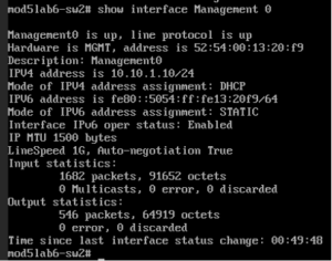
Step 3: Go to Switch 2 and check if interface Management 0 get IP Address via DHCP.
Go to Switch 2 and check if interface Management 0 (eth0) get IP address from DHCP using “show interface Management 0” command in sonic-cli.

Hints and tips
- Default credentials: admin / YourPaSsWoRd
- Be cautious about where you want to configure DHCP-Relay, remember to use the correct interface!
- Double-check every IP address if they are assigned correctly!
Answer
The purpose of the laboratory is to practice creating MCLAGs and PortChannels and how to use them in real environment.
Step 1: Assign IP Addresses on all of the Routers.
R-1
interface Ethernet 1
 ip address 10.10.10.101/24
 no shutdown
interface Ethernet 0
ip address 10.10.1.2/24
no shutdownStep 2: Configure Static Routes on each Router.
R-1
interface Ethernet 0
 ip dhcp-relay 10.10.10.100
Step 3: Go to Switch 2 and check if interface Management 0 get IP Address via DHCP.
Ip dhcp example: