
When designing a modern data center network with Enterprise SONiC, one of the most critical decisions is how to connect your servers to the network fabric. The host attachment model you choose impacts everything from redundancy and failover times to traffic distribution and application performance. In this article, I’ll explore the various host attachment models supported by Enterprise SONiC, including their benefits, trade-offs, and implementation considerations.
As a network architect who has deployed multiple SONiC fabrics, I’ve found that understanding these attachment models thoroughly helps avoid costly redesigns later. Let’s dive into the options available in Enterprise SONiC and how to select the right one for your environment.
Host Attachment Models Overview
Enterprise SONiC supports several host attachment models that cater to different redundancy and performance requirements. The choice of attachment model typically depends on server operating systems, NIC capabilities, and application requirements.
It’s worth noting that convergence and failover times are heavily influenced by the implementation of the NIC teaming software. While network teams configure the switch side, server/application teams are responsible for choosing the best convergence algorithm for each server.
Let’s examine the three primary host attachment models supported and validated in Enterprise SONiC:
Single-homed Attachment
Single-homed attachment is the simplest model where a host connects to a single leaf switch using either a single physical link or a Port-Channel (link aggregation).
Key characteristics: – Simplest configuration – Lowest cost (uses minimum ports) – No redundancy at switch level – Vulnerable to both link and device failures
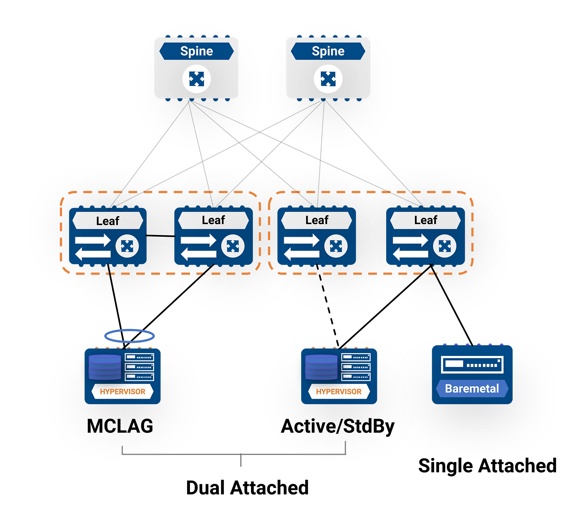
Figure 1: Single-homed attachment model
While Enterprise SONiC supports this model, it’s important to note that this design lacks redundancy. If the leaf switch fails or requires maintenance, the connected hosts will lose network connectivity. For this reason, single-homed attachment is typically only used for non-critical workloads or in environments where cost constraints outweigh redundancy requirements.
Dual-homed Attachment
Dual-homed attachment provides redundancy by connecting a host to two leaf switches. This model offers both link and device level redundancy, making it suitable for most production workloads.
Enterprise SONiC supports two primary types of dual-homed attachments:
MCLAG (Multi-Chassis Link Aggregation Group)
In an MCLAG configuration: – LACP runs between the server and MCLAG peer switches to form a multi-chassis port channel – From the server OS perspective, the physical links create a single logical link – LACP bundles the links together if they’re compatible – Server NICs must be capable of sensing and handling single port failures and redirecting traffic to non-failed ports.
MCLAG provides active-active forwarding across both leaf switches, maximizing bandwidth utilization while providing redundancy.
Active/Standby NIC Teaming
In this configuration: – The server typically has two MAC addresses (one for the active NIC, one for the passive NIC) – From the network perspective, MAC addresses associated with dual-NIC systems may change port/switch during a failover – This is a normal event, but traffic to some addresses may be black-holed until traffic originated by them is sent to the fabric – To overcome this situation, end-devices must send Gratuitous ARP packets immediately after switchover to update the network.
Active/standby teaming provides redundancy but doesn’t utilize the bandwidth of both links simultaneously during normal operation.
Routed Links with ECMP
The third model represents a significant architectural shift from traditional data center designs. Instead of Layer 2 connectivity between hosts and leaf switches, this model uses Layer 3 routing all the way to the host.
Key characteristics: – Completely eliminates Layer 2 from the data center network – Hosts run BGP with multiple leaf switches – Switches only advertise a default route towards hosts – Hosts only advertise specific routes – No MCLAG peering required between switches – Supports peering with more than 2 switches for better load-balancing and redundancy
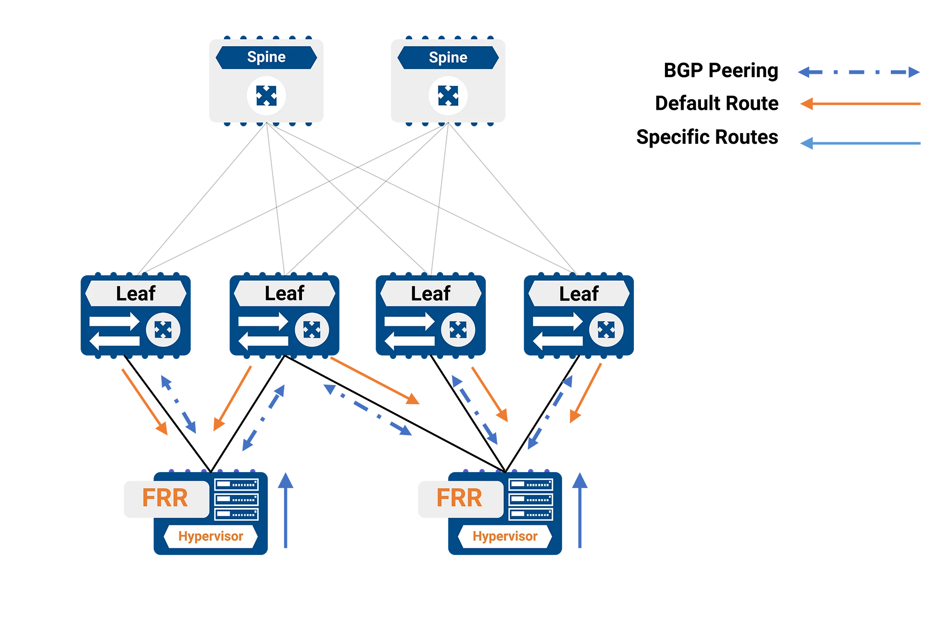
Figure 2: L3 Host Attachment Model
This approach has become increasingly popular as merchant silicon (led by Broadcom) has enabled routing at the same performance and price point as bridging. Open-source routing stacks for hosts like FRR are freely available and considered stable and mature.
Implementation Considerations
When to Choose Single-homed
Despite its lack of redundancy, single-homed attachment might be appropriate in these scenarios: – Development or test environments – Non-critical workloads – Budget-constrained deployments – Temporary or transitional deployments
When to Choose Dual-homed with MCLAG
MCLAG is ideal when: – You need active-active forwarding across both links – Your applications require Layer 2 adjacency between hosts – You want to maximize bandwidth utilization – Your server OS supports LACP – You prefer a traditional Layer 2 network design
When to Choose Routed Links with ECMP
The Layer 3 approach works best when: – You want to completely eliminate spanning tree and Layer 2 domains – Your applications don’t require Layer 2 adjacency between hosts (or you can use host-based overlays) – You need maximum scalability – You want to connect to more than two leaf switches – Your hosts can run routing protocols like BGP
It’s important to note that the Layer 3 design doesn’t provide Layer 2 adjacency between hosts. If this is required, host-based overlays would be needed.
Configuration Examples
Let’s look at some simplified configuration examples for each model. These are based on the Enterprise SONiC reference architecture.
MCLAG Configuration Example
Here’s a basic MCLAG configuration on two leaf switches:
Leaf 1:
mclag gateway-mac 00:00:00:11:22:33 mclag domain 1 source-ip 192.168.0.1 peer-ip 192.168.0.2 peer-link PortChannel100 mclag-system-mac 00:00:00:11:22:33 keepalive-interval 1 session-timeout 30 interface PortChannel 1 switchport trunk allowed Vlan add 10 no shutdown mclag 1
Leaf 2:
mclag gateway-mac 00:00:00:11:22:33 mclag domain 1 source-ip 192.168.0.2 peer-ip 192.168.0.1 peer-link PortChannel100 mclag-system-mac 00:00:00:11:22:33 keepalive-interval 1 session-timeout 30 interface PortChannel 1 switchport trunk allowed Vlan add 10 no shutdown mclag 1
Layer 3 ECMP Configuration Example
For the Layer 3 approach, you would configure BGP on both the leaf switches and the hosts:
Leaf Switch:
router bgp 65101 router-id 192.168.0.1 address-family ipv4 unicast redistribute connected maximum-paths 32 maximum-paths ibgp 32 neighbor 10.1.1.10 remote-as 65201 address-family ipv4 unicast route-map DEFAULT-ONLY out
Host (using FRR):
router bgp 65201 bgp router-id 10.1.1.10 neighbor 10.1.1.1 remote-as 65101 neighbor 10.1.1.2 remote-as 65101 address-family ipv4 unicast network 10.1.1.10/32
Best Practices
Based on the Enterprise SONiC reference architecture, here are some best practices for host attachment:
- For MCLAG deployments:
- Configure uplinks tracking to prevent traffic black-holing during uplink failures
- Use the same MCLAG system MAC address across all MCLAG domains in the fabric
- Ensure consistent VLAN configurations across MCLAG peers
- For Layer 3 ECMP deployments:
- Use eBGP between hosts and leaf switches for simpler configuration
- Configure leaf switches to only advertise a default route to hosts
- Configure hosts to only advertise specific routes
- Use BFD for faster failure detection
- General recommendations:
- Match the server team’s NIC teaming strategy with the appropriate switch configuration
- Document the attachment model used for each server type
- Test failover scenarios during maintenance windows
Conclusion
The host attachment model you choose for your Enterprise SONiC deployment has significant implications for network reliability, performance, and operational complexity.
Single-homed attachment offers simplicity but lacks redundancy. Dual-homed attachment with MCLAG provides both redundancy and active-active forwarding but requires Layer 2 domains. Layer 3 ECMP eliminates Layer 2 domains entirely, offering maximum scalability and redundancy at the cost of requiring routing on the hosts.
Modern data center designs are increasingly moving toward Layer 3 to the host where possible, but many organizations still require Layer 2 adjacency for certain applications. Enterprise SONiC’s flexibility allows you to implement the attachment model that best suits your specific requirements.
When planning your SONiC deployment, work closely with your server and application teams to ensure the chosen attachment model aligns with their requirements for redundancy, failover times, and application connectivity.