Currently Empty: 0.00 €
SONiC
CLOS Architecture in Data Centers with Enterprise SONiC
Listen to this Article
In today’s rapidly evolving data center landscape, traditional three-tier network architectures are being replaced by more scalable and efficient designs. As someone who’s worked with various network architectures over the years, I’ve witnessed firsthand how modern applications have dramatically changed traffic patterns within data centers. The shift from monolithic applications to microservices-based architectures has resulted in a significant increase in east-west traffic—communication between different nodes of an application rather than north-south traffic to external networks.
This fundamental change in traffic patterns has driven the adoption of CLOS or Leaf-Spine architecture, a design pioneered by web-scale companies and now widely accepted as the standard for modern data center fabrics. Enterprise SONiC (Software for Open Networking in the Cloud), Broadcom’s distribution of the open-source network operating system, provides robust support for implementing CLOS architectures. In this article, I’ll explore the fundamentals of CLOS architecture and how Enterprise SONiC enables its deployment in data center environments.
Understanding CLOS Architecture
CLOS architecture, named after the mathematician Charles Clos, is a non-blocking, multistage switching architecture that provides predictable latency and high bandwidth between any two endpoints. In modern data centers, this translates to a Leaf-Spine topology that offers several advantages over traditional three-tier designs.
Key Components of CLOS Architecture
A typical CLOS architecture consists of two primary layers:
- Leaf Layer: These switches connect directly to end devices like servers, storage, and other network appliances. Every leaf switch connects to every spine switch, creating multiple paths through the network.
- Spine Layer: These switches form the backbone of the network and connect only to leaf switches, never directly to end devices or other spine switches.
In larger deployments, a third layer called “Super-Spine” may be added to create a five-stage CLOS architecture, enabling even greater scalability.
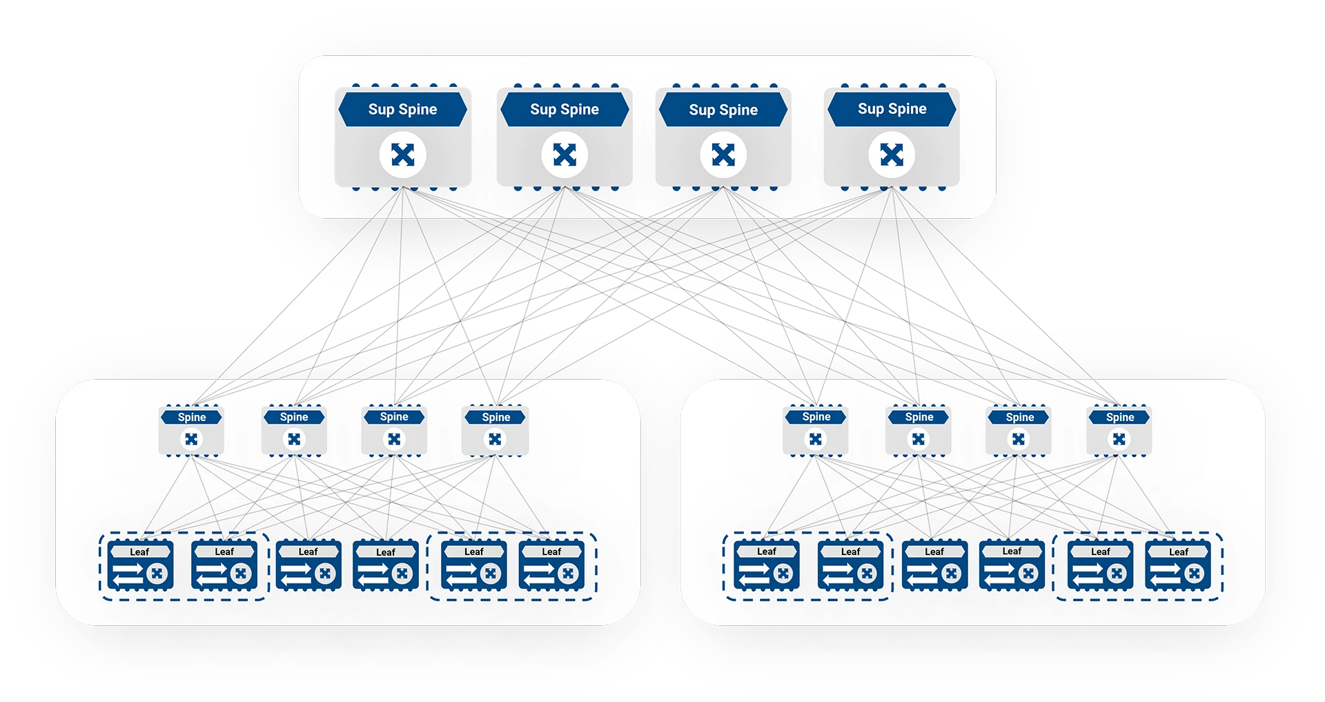
Figure 1: 5 stage CLOS Architecture
The beauty of this design lies in its simplicity and scalability. As your data center grows, you can add more leaf switches to accommodate more servers or more spine switches to increase bandwidth between leaf switches. This modular approach allows for incremental growth without requiring a complete redesign of the network.
Underlay Network in CLOS Architecture
The underlay network in a CLOS architecture provides IP connectivity between all devices in the fabric. Enterprise SONiC supports two primary routing protocols for the underlay: BGP and OSPF.
BGP as Underlay
When using BGP as the underlay routing protocol, Enterprise SONiC follows RFC7938 for design guidelines. The key principles include:
- Using EBGP (External BGP) in the underlay
- Assigning a single ASN (Autonomous System Number) to all Super-spines (in five-stage CLOS)
- Assigning a single ASN to all Spines in a POD
- Assigning unique ASNs to all Leaf switches
This approach creates a clear hierarchy and simplifies troubleshooting while providing excellent scalability.
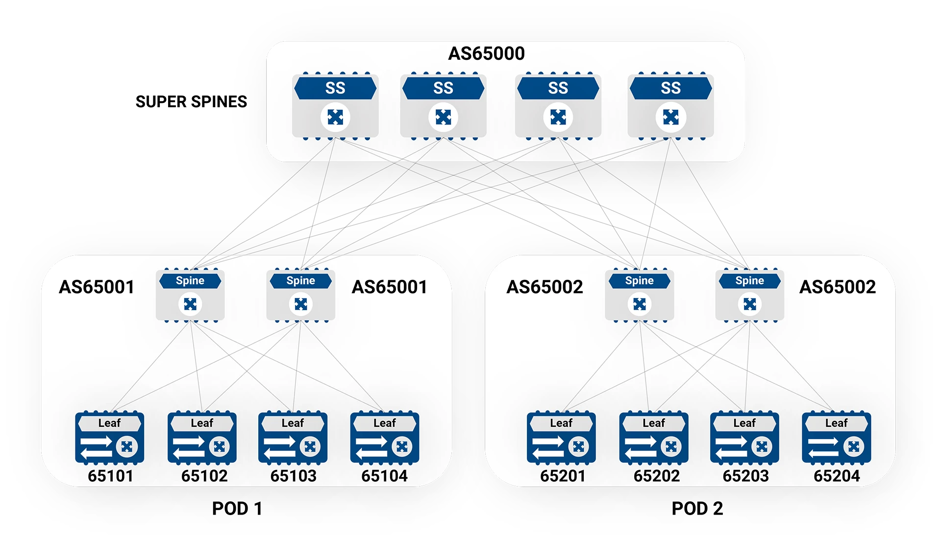
Figure 2: Sample ASN numbering in a Three-tier CLOS
OSPF as Underlay
While BGP is the preferred routing protocol for large-scale deployments, some organizations prefer using OSPF as the underlay protocol, particularly when they want to maintain separation between underlay and overlay routing protocols. Enterprise SONiC supports OSPF as an underlay with the following design features:
- Single OSPF area across all links
- Support for IP Unnumbered (simplifying IP address management)
- Support for /31 subnets
- BFD (Bidirectional Forwarding Detection) for fast failover
- Peer authentication for security
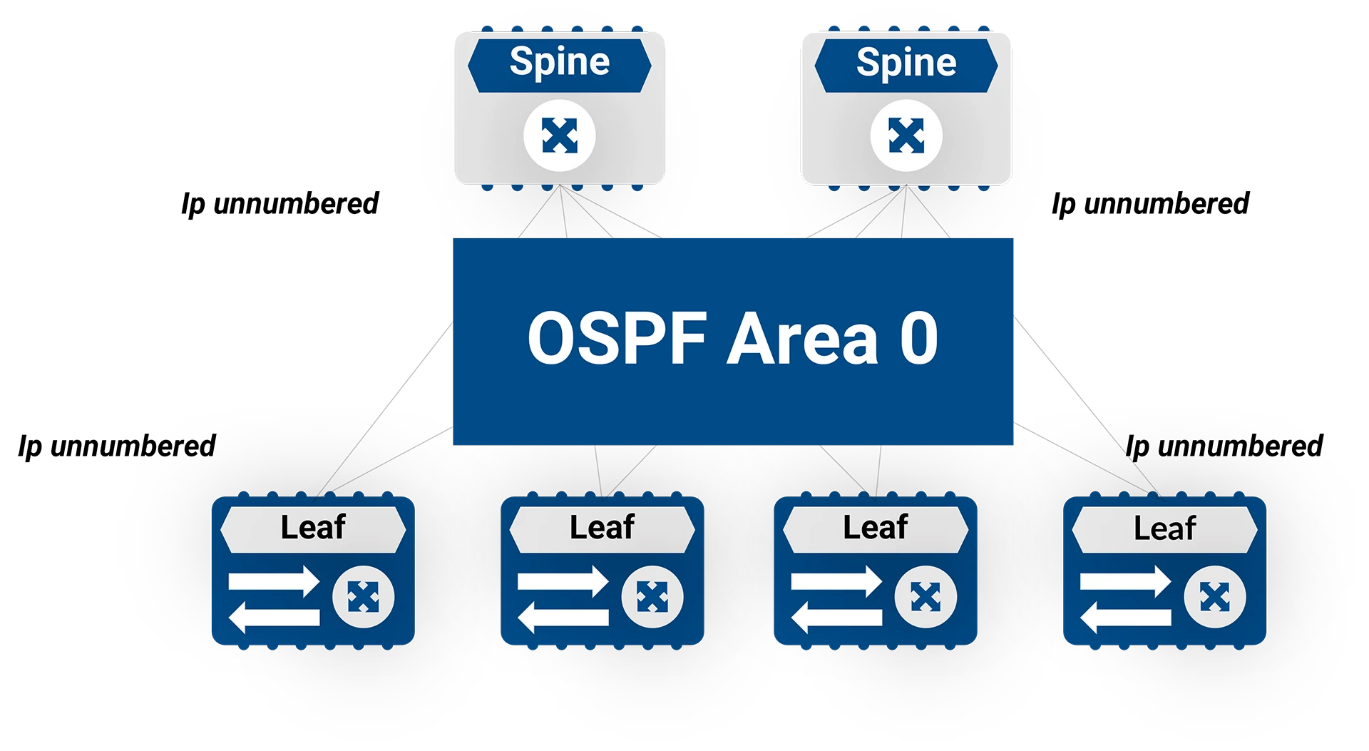
Figure 3: OSPF as underlay routing protocol
Overlay Network in CLOS Architecture
The overlay network provides network virtualization by abstracting the underlying physical network. In Enterprise SONiC, VXLAN (Virtual Extensible LAN) is the primary overlay technology.
VXLAN
VXLAN allows building Layer 2 virtual networks over Layer 3 infrastructure. It uses UDP over IP as the encapsulation method, which enables existing network equipment to load-balance packets over multiple paths—a common requirement in data center networks.
With a 24-bit VNID (VXLAN Network Identifier) field, VXLAN provides up to 16 million virtual identifiers, far exceeding the 4,096 VLAN limit of traditional networks. This makes it ideal for large-scale multi-tenant environments.
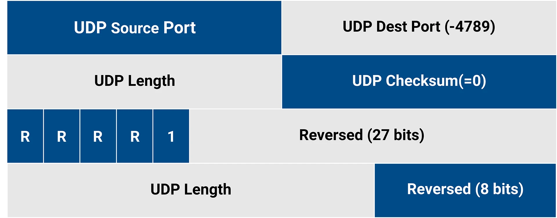
Table 1: VXLAN Header
One clever aspect of VXLAN implementation is how it handles ECMP (Equal-Cost Multi-Path) routing. When a packet is tunneled across a VXLAN overlay, the ingress VTEP (VXLAN Tunnel Endpoint) sets the source port to be the hash of the five-tuple of the underlying payload header. This introduces entropy that enables effective load balancing of workload traffic across the VXLAN overlay.
BGP EVPN
Traditional VXLAN deployments used a flood-and-learn approach for data transmission, which wasn’t optimal for large-scale deployments. BGP EVPN (Ethernet VPN) provides a control plane for network virtualization, making VXLAN deployments more efficient and scalable.
EVPN uses BGP as its control protocol and VXLAN for packet encapsulation in the data center. It connects Layer 2 network segments separated by a Layer 3 network by building a virtual Layer 2 network overlay over the Layer 3 network.
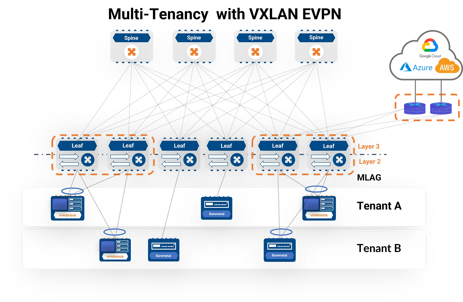
Figure 4: Multi-tenancy with VXLAN EVPN
Enterprise SONiC’s implementation of EVPN supports several route types, including:
- Route Type 2: Carries MAC, IP, and VNI information to advertise reachability to specific MAC/IP addresses in a virtual network
- Route Type 3: Advertises VTEP’s interest in virtual networks
- Route Type 5: Advertises IP prefixes and their associated VRFs
Some notable features of Enterprise SONiC’s BGP EVPN implementation include:
- Ingress replication for BUM (Broadcast, Unknown Unicast, Multicast) traffic
- LVTEP (Logical VTEP) with MCLAG for dual-attached hosts
- Support for both Symmetric and Asymmetric VXLAN Routing methods
- Automatic handling of next-hop address preservation for virtual network routes
- Graceful handling of MAC/Neighbor moves using the BGP Extended community “MAC Mobility”
- ARP/ND Suppression to reduce BUM traffic
- MAC Move Dampening to handle problematic situations caused by faulty NICs
Conclusion
CLOS architecture has become the de facto standard for modern data center networks, providing the scalability, performance, and flexibility needed to support today’s distributed applications. Enterprise SONiC offers a comprehensive set of features to implement CLOS architectures, supporting both BGP and OSPF as underlay protocols and VXLAN with BGP EVPN as the overlay.
The combination of a non-blocking physical topology with powerful network virtualization capabilities creates a foundation that can support the most demanding workloads while providing operational simplicity and future scalability. Whether you’re building a new data center or modernizing an existing one, understanding the principles of CLOS architecture and how Enterprise SONiC implements them is essential for designing a network that can meet both current and future requirements.
As we continue to see the evolution of applications toward even more distributed architectures, the importance of a well-designed network fabric will only increase. CLOS architecture, implemented with Enterprise SONiC, provides a solid foundation for this future.