Currently Empty: 0.00 €
SONiC hands-on training - Module 5 - Lab 3 - Static Routes Configuration
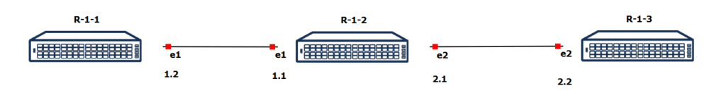
You are a network engineer tasked with configuring static routing in a linear topology involving three routers: R-1-1, R-1-2, and R-1-3. The routers are connected via Ethernet interfaces, as shown in the diagram. Your goal is to ensure full connectivity between all routers by configuring appropriate static routes on each device.
- Router R-1-1 is connected to Router R-1-2 via interface e1 with IP addresses 192.168.1.2 (R-1-1) and 192.168.1.1 (R-1-2).
- Router R-1-2 connects to Router R-1-3 via interface e2 with IP addresses 192.168.2.1 (R-1-2) and 192.168.2.2 (R-1-3).
Instruction
Step 1: Assign IP Addresses on all of the Routers
Log in to the routers (R-1-1, R-1-2, R-1-3) using the default credentials and use the CLI. Assign the correct IP addresses to each Ethernet interface that connects to another router.
Router R-1-1:
- Ethernet1 – 192.168.1.2/24
Router R-1-2:
- Ethernet1 – 192.168.1.1/24
- Ethernet2 – 192.168.2.1/24
Router R-1-3:
- Ethernet2 – 192.168.2.2/24
Step 2: Configure Static Routes on each Router + additional floating static route to 192.168.3.0 to blackhole
After assigning IP addresses, configure static routes to ensure connectivity between all routers. Create additional static route to 192.168.3.0 remember – It needs to be blackhole!
Step 3: Verify Static Route Configuration
After configuring the static routes, verify the configuration on each router using command “show ip route”. Could you tell what the letters means under “Codes”?
- Default credentials: admin / YourPaSsWoRd
- Default credentials: admin / YourPaSsWoRd
- Be cautious about the ip routes – Remember the order of the ip addresses!
- Double-check every IP address if they are assigned correctly!
- The names of the virtual computers are different in remote access to those shown on the topology. Virtual computers and their counterparts in remote access are motioned below:
- R-1-1 – mod5lab3-sw1
- R-1-2 – mod5lab3-sw2
- R-1-3 – mod5lab3-sw3
The purpose of the laboratory is to practice creating MCLAGs and PortChannels and how to use them in real environment.
Step 1: Assign IP Addresses on all of the Routers.
Router 1
interface Ethernet1
ip address 192.168.1.2/24
no shutdown
Router 2
interface Ethernet1
ip address 192.168.1.1/24
no shutdown
interface Ethernet2
ip address 192.168.2.1/24
no shutdown
Router 3
interface Ethernet2
ip address 192.168.2.2/24
no shutdown
Step 2: Configure Static Routes on each Router.
Router 1
ip route 192.168.2.0/24 192.168.1.1
ip route 192.168.3.0/24 blackhole
Router 2
ip route 192.168.1.0/24 192.168.1.2
ip route 192.168.2.0/24 192.168.2.2
ip route 192.168.3.0/24 blackhole
Router 3
ip route 192.168.1.0/24 192.168.2.1
ip route 192.168.3.0/24 blackhole
Step 3: Verify Static Route Configuration
show ip route example: – Router-1-2
sonic# show ip route
Codes: K – kernel route, C – connected, S – static, B – BGP, O – OSPF
> – selected route, * – FIB route, q – queued route, r – rejected route
Destination Gateway Dist/Metric Last Update
——————————————————————————————————————————–
S 192.168.1.0/24 via 192.168.1.2 1/0 00:05:42 ago
C>* 192.168.1.0/24 Direct Ethernet1 0/0 00:05:46 ago
S 192.168.2.0/24 via 192.168.2.2 1/0 00:05:37 ago
C>* 192.168.2.0/24 Direct Ethernet2 0/0 00:05:43 ago