Currently Empty: 0.00 €
SONiC hands-on training - Module 5 - Lab 2 – BGP Configuration
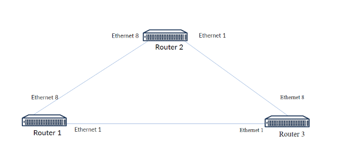
You are a network engineer tasked with configuring a simple BGP (Border Gateway Protocol) routing protocol in a triangular topology involving three routers:
- Router 1,
- Router 2
- Router 3.
The routers are connected via Ethernet interfaces, as shown in the diagram.
Instruction
Step 1: Assign IP Addresses on all of the Routers.
Log in to the switches (Router 1, Router 2, Router 3) using the default credentials, use the Klish CLI. Assign a proper IP Addressess to each of the port that is connected to other Router. Create an Loopback interface and assign a IP address to that interface.
Router 1:
- Ethernet 1 – 1.1.1.1/31
- Ethernet 8 – 1.1.1.2/31
- Loopback0 – 192.168.0.1/32
Router 2:
- Ethernet1 – 1.1.1.4/31
- Ethernet8 – 1.1.1.3/31
- Loopback0 – 192.168.0.2/32
Router 3
- Ethernet1 – 1.1.1.0/31
- Ethernet8 – 1.1.1.5/31
- Loopback0 – 192.168.0.3/32
Step 2: Create BGP on every router with different AS number and configure a router id for the BGP process
After you configured all of the interfaces on the router, you need to create an BGP process on a every router and configure a proper router-id on every router with created BGP session.
Step 3: Activate IPv4 unicast address-family and configure every neighbor.
Activate address-family on every BGP session – This must be done on the neighbours (IPv4 unicast address family). You will need to advertise local interfaces, also in the IPv4 unicast address-family.
Step 4: Verify BGP configuration.
You need to check the BGP configuration after the configuration – Make sure everything is set all right! To do that, you need to type in console “show bgp ipv4 unicast summary”
Step 5: Do the connectivity test.
From each router, ping the Loopback interfaces of the other two routers to confirm end-to-end connectivity
- Default credentials: admin / YourPaSsWoRd
- Be cautious about the BGP AS number that you are using – In this case, it needs to be different!
- Double-check every IP address if they are assigned correctly!
- The names of the virtual computers are different in remote access to those shown on the topology. Virtual computers and their counterparts in remote access are motioned below:
- Router1 – mod5lab2-sw1
- Router2 – mod5lab2-sw2
- Router3 – mod5lab2-sw3
The purpose of the laboratory is to practice creating MCLAGs and PortChannels and how to use them in real environment.
Step 1: Assign IP Addresses on all of the Routers.
Router 1
interface Loopback 0
ip address 192.168.0.1/32
interface Ethernet1
ip address 1.1.1.1/31
no shutdown
interface Ethernet8
ip address 1.1.1.2/31
Router 2
interface Loopback 0
ip address 192.168.0.2/32
interface Ethernet1
ip address 1.1.1.4/31
no shutdown
interface Ethernet8
ip address 1.1.1.3/31
no shutdown
Router 3
interface Loopback 0
ip address 192.168.0.3/32
interface Ethernet1
ip address 1.1.1.0/31
no shutdown
interface Ethernet8
ip address 1.1.1.5/31
no shutdown
Step 2 & 3: Create BGP on every router with different AS number, configure a router id for the BGP process, activate address-family and configure every neighbor.
Router 1
router bgp 65100
router-id 192.168.0.1
address-family ipv4 unicast
redistribute connected
neighbor 1.1.1.0
remote-as 65102
address-family ipv4 unicast
activate
neighbor 1.1.1.3
remote-as 65101
address-family ipv4 unicast
activate
Router 2
router bgp 65101
router-id 192.168.0.2
address-family ipv4 unicast
redistribute connected
neighbor 1.1.1.2
remote-as 65100
address-family ipv4 unicast
activate
neighbor 1.1.1.5
remote-as 65102
address-family ipv4 unicast
activate
Router 3
router bgp 65102
router-id 192.168.0.3
address-family ipv4 unicast
redistribute connected
neighbor 1.1.1.1
remote-as 65100
address-family ipv4 unicast
activate
neighbor 1.1.1.4
remote-as 65101
address-family ipv4 unicast
activate
Step 4: Verify BGP Configuration
show bgp ipv4 unicast summary example:
sonic# show bgp ipv4 unicast summary
BGP router identifier 1.1.1.1, local AS number 100
Neighbor V AS MsgRcvd MsgSent InQ OutQ Up/Down State/PfxRcd
192.168.0.2 4 200 18480 18486 0 0 1w5d19h 8
192.168.0.3 4 200 18510 18502 0 0 02:49:01 11
Step 5: Check the connectivity between the routers.
Router 1:
# Ping Router 2’s Loopback
ping 192.168.0.2
# Ping Router 3’s Loopback
ping 192.168.0.3
# Ping Router 2’s Ethernet Interface (1.1.1.4)
ping 1.1.1.4
# Ping Router 3’s Ethernet Interface (1.1.1.0)
ping 1.1.1.0
Expected Output:
All pings should show success with low latency
Router 2:
# Ping Router 1’s Loopback
ping 192.168.0.1
# Ping Router 3’s Loopback
ping 192.168.0.3
# Ping Router 1’s Ethernet Interface (1.1.1.1)
ping 1.1.1.1
# Ping Router 3’s Ethernet Interface (1.1.1.5)
ping 1.1.1.5
Expected Output:
All pings should show success with low latency
Router 3:
# Ping Router 1’s Loopback
ping 192.168.0.1
# Ping Router 2’s Loopback
ping 192.168.0.2
# Ping Router 1’s Ethernet Interface (1.1.1.2)
ping 1.1.1.2
# Ping Router 2’s Ethernet Interface (1.1.1.3)
ping 1.1.1.3
Expected Output:
All pings should show success with low latency