Currently Empty: 0.00 €
Module 3 – LAB 4 - VLAN Configuration
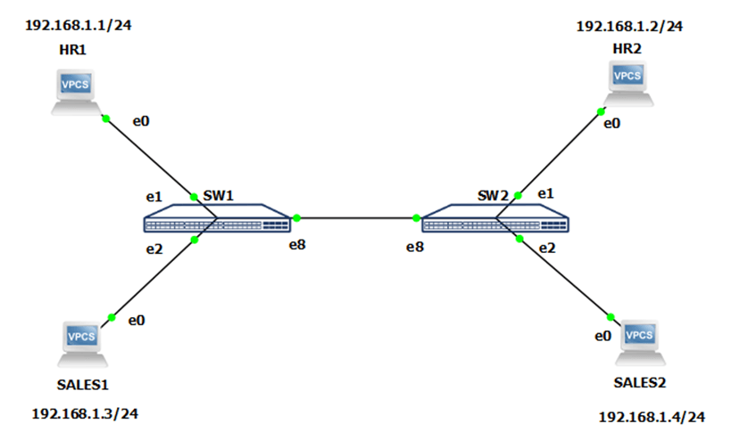
You are a network engineer tasked with configuring VLANs. You have two departments: HR and Sales. Each department is on two floors. You need to separate the two departments from each other so that only your department can communicate with each other – HR can’t communicate with Sales, and Sales can’t communicate with HR. The PCs are already configured, so all you need to do is configure the switches. HR should be in VLAN 10, and SALES should be in VLAN 20.
Step 1: Check VLANs and create a new VLANs – 10 and 20.
- Log in to the switches (SW1, SW2) using the default credentials, use the Klish CLI. Create a new VLANs – 10 for HR, and 20 for Sales departments, after that view the current VLANs that exists on this switch.
- Step 2: Configure the access ports on both switches.
Configure Ethernet1 and Ethernet2 of both switches (SW1, SW2) to access ports. Ethernet1 ports should be in VLAN 10, and Ethernet2 ports should be in VLAN 20. After that, check again current VLANs.
- Step 3: Configure the trunk port on both switches.
Configure the Ethernet8 port, which should be the trunk port. Allow all VLANs on that port.
- Step 4: Check that everything is working using the PING command.
Use the ping command to mutually ping the devices from HR1 to HR2, and from SALES1 to SALES2

- Default credentials: admin / YourPaSsWoRd
- Remember to allow all VLANs to be sent through trunk port
- PCs should’ve been connected to access ports, not the trunk one.
- In SONiC, the subnet mask 255.255.255.0 is represented in the format of x.x.x.x/24. This is because the number 24 represents the number of bits set to 1 in the subnet mask, which is equivalent to 255.255.255.0 in dotted decimal notation.
- The names of the virtual computers are different in remote access to those shown on the topology. Virtual computers and their counterparts in remote access are motioned below:
- HR1 – mod3lab4-vpc1
- HR2 – mod3lab4-vpc3
- SALES1 – mod3lab4-vpc2
- SALES2 – mod3lab4-vpc4
- Credentials for Virtual computers are login: root password: route2open
The purpose of the laboratory is to practice creating VLANs and how to use them in real environment.
Step 1: Check VLANs and create a new VLANs – 10 and 20.
SW1 & SW2
1. sonic# configure terminal
2. sonic(config)# interface Vlan 10
3. sonic(config–if–Vlan10)# exit
4. sonic(config)# interface Vlan 20
5. sonic(config–if–Vlan20)# exit
6. sonic(config)# exit
7. sonic# show Vlan
8. Q: A – Access (Untagged), T – Tagged
9. NUM Status Q Ports Autostate Dynamic
10. 10 Inactive Enable
11. 20 Inactive Enable
Step 2: Configure the access ports on both switches
SW1 & SW2
1. sonic# configure terminal
2. sonic(config)# interface Ethernet1
3. sonic(config–if–Ethernet1)# switchport access Vlan 10
4. sonic(config–if–Ethernet1)# no shutdown
5. sonic(config–if–Ethernet1)# exit
6. sonic(config)# interface Ethernet2
7. sonic(config–if–Ethernet2)# switchport access Vlan 20
8. sonic(config–if–Ethernet2)# no shutdown
9. sonic(config–if–Ethernet2)# exit
10. sonic# show Vlan
11. Q: A – Access (Untagged), T – Tagged
12. NUM Status Q Ports Autostate Dynamic
13. 10 Active Enable
14. 20 Active Enable
Step 3: Configure the trunk port on both switches.
SW1 & SW2:
1. sonic# configure terminal
1. sonic(config)# interface Ethernet8
2. sonic(config–if–Ethernet8)# switchport trunk allowed vlan all
3. sonic(config–if–Ethernet8)# no shutdown
4. sonic(config–if–Ethernet8)# exit
Step 4: Check that everything is working using the PING command.
HR1 to HR2:
1. HR1> ping 192.168.1.1 <- That’s IP for HR1
2.
3. 192.168.1.1 icmp_seq=1 ttl=64 time=0.001 ms
4. 192.168.1.1 icmp_seq=2 ttl=64 time=0.001 ms
5. 192.168.1.1 icmp_seq=3 ttl=64 time=0.001 ms
6. 192.168.1.1 icmp_seq=4 ttl=64 time=0.001 ms
7. 192.168.1.1 icmp_seq=5 ttl=64 time=0.001 ms
9. HR1> ping 192.168.1.3 <- That’s IP for SALES1
11. host (192.168.1.3) not reachable
13. HR1> ping 192.168.1.2 <- That’s IP for HR2
15. 84 bytes from 192.168.1.2 icmp_seq=1 ttl=64 time=8.142 ms
16. 84 bytes from 192.168.1.2 icmp_seq=2 ttl=64 time=9.225 ms
17. 84 bytes from 192.168.1.2 icmp_seq=3 ttl=64 time=7.310 ms
18. 84 bytes from 192.168.1.2 icmp_seq=4 ttl=64 time=6.748 ms
19. 84 bytes from 192.168.1.2 icmp_seq=5 ttl=64 time=7.339 ms
21. HR1> ping 192.168.1.4 <- That’s IP for SALES2
23. host (192.168.1.4) not reachable
SALES1 to SALES2:
1. SALES1> ping 192.168.1.3 <- That’s IP for SALES1
3. 192.168.1.3 icmp_seq=1 ttl=64 time=0.001 ms
4. 192.168.1.3 icmp_seq=2 ttl=64 time=0.001 ms
5. 192.168.1.3 icmp_seq=3 ttl=64 time=0.001 ms
6. 192.168.1.3 icmp_seq=4 ttl=64 time=0.001 ms
7. 192.168.1.3 icmp_seq=5 ttl=64 time=0.001 ms
9. SALES1> ping 192.168.1.4 <- That’s IP for SALES2
11. 84 bytes from 192.168.1.4 icmp_seq=1 ttl=64 time=8.816 ms
12. 84 bytes from 192.168.1.4 icmp_seq=2 ttl=64 time=10.120 ms
13. 84 bytes from 192.168.1.4 icmp_seq=3 ttl=64 time=11.251 ms
14. 84 bytes from 192.168.1.4 icmp_seq=4 ttl=64 time=9.931 ms
16. SALES1> ping 192.168.1.1 <- That’s IP for HR1
18. host (192.168.1.1) not reachable
20. SALES1> ping 192.168.1.2 <- That’s IP for HR2
22. host (192.168.1.2) not reachable


