Currently Empty: 0.00 €
SONiC hands-on training - Module 5 - Lab 4 - BGP with BFD Configuration
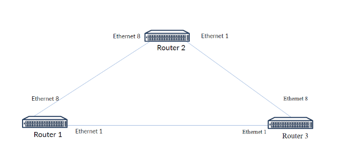
You are a network engineer tasked with configuring a simple BGP (Border Gateway Protocol) routing protocol in a triangular topology involving three routers:
- Router 1,
- Router 2,
- Router 3.
You need to enable BFD in BGP protocol. The routers are connected via Ethernet interfaces, as shown in the diagram.
Step 1: Assign IP Addresses on all of the Routers.
Log in to the switches (Router 1, Router 2, Router 3) using the default credentials, use the Klish CLI. Assign a proper IP Addressess to each of the port that is connected to other Router. Create an Loopback interface and assign a IP address to that interface.
Router 1:
- Ethernet 1 – 1.1.1.1/31
- Ethernet 8 – 1.1.1.2/31
- Loopback0 – 192.168.0.1/32
Router 2:
- Ethernet1 – 1.1.1.4/31
- Ethernet8 – 1.1.1.3/31
- Loopback0 – 192.168.0.2/32
Router 3
- Ethernet1 – 1.1.1.0/31
- Ethernet8 – 1.1.1.5/31
- Loopback0 – 192.168.0.3/32
Step 2: Create BGP on every router with different AS number and configure a router id for the BGP process
After you configured all of the interfaces on the router, you need to create an BGP process on a every router and configure a proper router-id on every router with created BGP session.
Step 3: Activate IPv4 unicast address-family and configure every neighbor.
Activate address-family on every BGP process – This must be done on the neighbours (IPv4 unicast address family). You will need to advertise local interfaces, also in the IPv4 unicast address-family. Configure BFD on each neighbor.
Step 4: Verify BGP and BFD configuration.
You need to check the BGP and BFD configuration after the configuration – Make sure everything is set all right! To do that, you need to type in console “show bgp ipv4 unicast summary”. If everything is okay, proceed further and check the BFD configuration using “show bfd peers” command.
Step 5: Do the connectivity test.
From each router, ping the Loopback interfaces of the other two routers to confirm end-to-end connectivity.
- Default credentials: admin / YourPaSsWoRd
- Be cautious about the BGP AS number that you are using – In this case, it needs to be different!
- Double-check every IP address if they are assigned correctly!
- The names of the virtual computers are different in remote access to those shown on the topology. Virtual computers and their counterparts in remote access are motioned below:
- Router1 – mod5lab4-sw1
- Router2 – mod5lab4-sw2
- Router3 – mod5lab4-sw3
The purpose of the laboratory is to practice creating MCLAGs and PortChannels and how to use them in real environment.
Step 1: Assign IP Addresses on all of the Routers.
Router 1
interface Loopback 0
ip address 192.168.0.1/32
exit
interface Ethernet1
ip address 1.1.1.1/31
no shutdown
exit
interface Ethernet8
ip address 1.1.1.2/31
No shutdown
exit
Router 2
interface Loopback 0
ip address 192.168.0.2/32
interface Ethernet1
ip address 1.1.1.4/31
no shutdown
interface Ethernet8
ip address 1.1.1.3/31
no shutdown
Router 3
interface Loopback 0
ip address 192.168.0.3/32
interface Ethernet1
ip address 1.1.1.0/31
no shutdown
interface Ethernet8
ip address 1.1.1.5/31
no shutdown
Step 2 & 3: Create BGP on every router with different AS number, configure a router id for the BGP process, activate address-family and configure every neighbor.
Router 1
router bgp 65100
router-id 192.168.0.1
address-family ipv4 unicast
redistribute connected
neighbor 1.1.1.0
remote-as 65102
bfd
address-family ipv4 unicast
activate
neighbor 1.1.1.3
remote-as 65101
bfd
address-family ipv4 unicast
activate
Router 2
router bgp 65101
router-id 192.168.0.2
address-family ipv4 unicast
redistribute connected
neighbor 1.1.1.2
remote-as 65100
bfd
address-family ipv4 unicast
activate
neighbor 1.1.1.5
remote-as 65102
bfd
address-family ipv4 unicast
activate
Router 3
router bgp 65102
router-id 192.168.0.3
address-family ipv4 unicast
redistribute connected
neighbor 1.1.1.1
remote-as 65100
bfd
address-family ipv4 unicast
activate
neighbor 1.1.1.4
remote-as 65101
bfd
address-family ipv4 unicast
activate
Step 4: Verify BGP and BFD Configuration
show bgp ipv4 unicast summary example:
sonic# show bgp ipv4 unicast summary
BGP router identifier 1.1.1.1, local AS number 100
Neighbor V AS MsgRcvd MsgSent InQ OutQ Up/Down State/PfxRcd
192.168.0.2 4 200 18480 18486 0 0 1w5d19h 8
192.168.0.3 4 200 18510 18502 0 0 02:49:01 11
show bfd peers example:
sonic# show bfd peers
BFD Peers:
peer 192.168.0.2 vrf default interface Ethernet8
ID: 2996261756
Remote ID: 1246817708
Passive mode: Disabled
Status: up ß
Uptime: 0 day(s), 0 hour(s), 9 min(s), 21 sec(s)
Diagnostics: ok
Remote diagnostics: ok
Peer Type: dynamic
Local timers:
Detect-multiplier: 3
Receive interval: 300ms ß
Transmission interval: 300ms
Echo transmission interval: 0ms
Remote timers:
Detect-multiplier: 3
Receive interval: 300ms
Transmission interval: 300ms
Echo transmission interval: 300ms
peer 192.168.0.3 vrf default interface Ethernet1
ID: 2996261756
Remote ID: 1246817708
Passive mode: Disabled
Status: up ß
Uptime: 0 day(s), 0 hour(s), 9 min(s), 21 sec(s)
Diagnostics: ok
Remote diagnostics: ok
Peer Type: dynamic
Local timers:
Detect-multiplier: 3
Receive interval: 300ms ß
Transmission interval: 300ms
Echo transmission interval: 0ms
Remote timers:
Detect-multiplier: 3
Receive interval: 300ms
Transmission interval: 300ms
Echo transmission interval: 300ms
Step 5: Check the connectivity between the routers.
Router 1:
# Ping Router 2’s Loopback
ping 192.168.0.2
# Ping Router 3’s Loopback
ping 192.168.0.3
# Ping Router 2’s Ethernet Interface (1.1.1.4)
ping 1.1.1.4
# Ping Router 3’s Ethernet Interface (1.1.1.0)
ping 1.1.1.0
Expected Output:
All pings should show success with low latency
Router 2:
# Ping Router 1’s Loopback
ping 192.168.0.1
# Ping Router 3’s Loopback
ping 192.168.0.3
# Ping Router 1’s Ethernet Interface (1.1.1.1)
ping 1.1.1.1
# Ping Router 3’s Ethernet Interface (1.1.1.5)
ping 1.1.1.5
Expected Output:
All pings should show success with low latency
Router 3:
# Ping Router 1’s Loopback
ping 192.168.0.1
# Ping Router 2’s Loopback
ping 192.168.0.2
# Ping Router 1’s Ethernet Interface (1.1.1.2)
ping 1.1.1.2
# Ping Router 2’s Ethernet Interface (1.1.1.3)
ping 1.1.1.3
Expected Output:
All pings should show success with low latency